
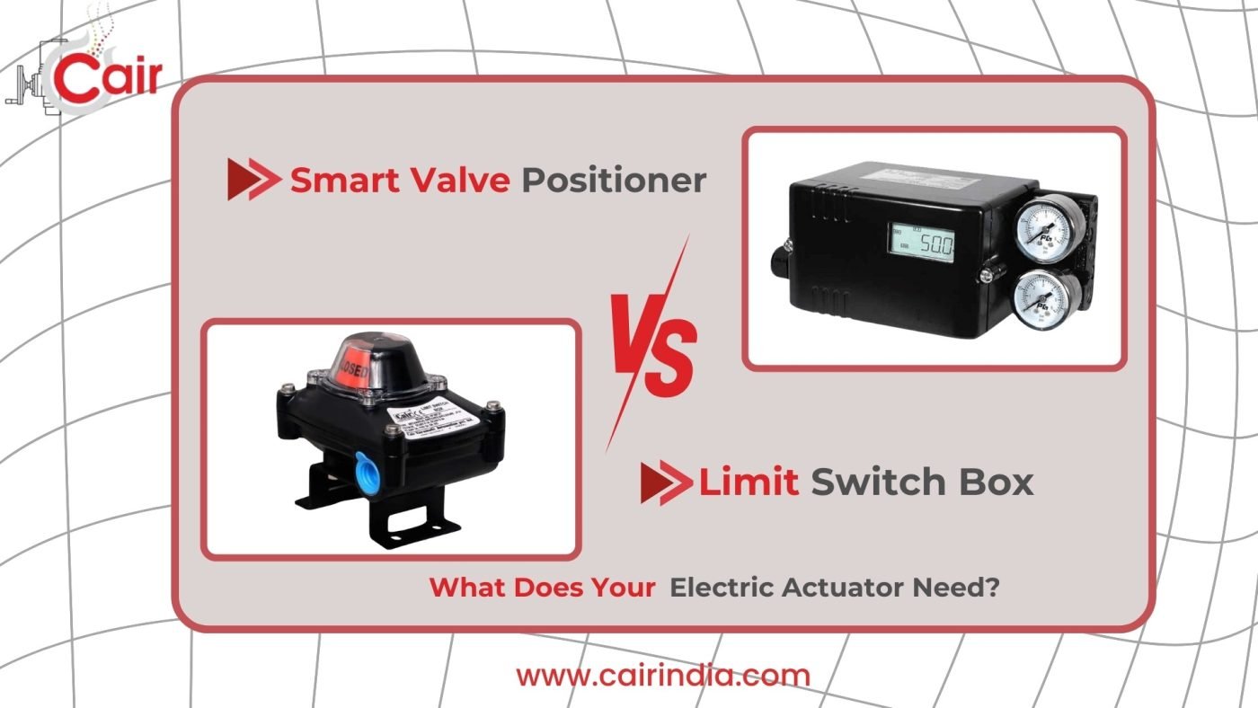
Ask ten instrumentation engineers in India what the difference is between a valve positioner and a limit switch box, and at least six of them will pause before answering. This is not a knowledge gap – it is a genuine architectural question that even experienced professionals revisit when sitting down to specify a new valve automation system.
Both devices mount on the same electric actuator. Both deal with valve position. Both send signals back to your control system. The product catalogues do not help much either – they describe specifications and part numbers, but rarely explain the functional purpose clearly enough to answer the real question: which one does my application actually need?
Getting this wrong has measurable consequences. Specify only a limit switch box on a modulating control application and your process parameter – flow, pressure, level – will drift continuously as the valve wanders from set point under load, because there is no correction loop. Specify only a positioner on a simple ON/OFF valve connected to a SCADA system and your PLC will never receive a reliable open/closed confirmation signal, leading to continuous nuisance alarms. According to the ISA-18.2 alarm management standard, incorrect or missing valve position feedback is one of the most persistent root causes of alarm floods in process plants – the kind that operators learn to ignore, which is exactly when real safety events go unnoticed [1].
India’s industrial automation market is growing fast – projected to reach USD 14.7 billion by 2028 at a 9.1% CAGR, driven by smart manufacturing investments, PLI scheme industries, and infrastructure expansion under programmes like Jal Jeevan Mission and AMRUT 2.0 [2]. As more Indian plants integrate SCADA, DCS, and IIoT platforms, the distinction between these two accessories becomes not just technically relevant but commercially critical – because the right combination directly determines whether your valve automation delivers reliable process control or merely the illusion of it.
This guide resolves the confusion completely. By the end, you will know exactly what each device does, when you need which one, and – crucially – when your application needs both at the same time.
The Fundamental Difference – Stated as Clearly as Possible
What a Limit Switch Box Does
A limit switch box reports where your valve is. It sends a discrete electrical signal – open or closed, yes or no, 24V or 0V – to your control system when the valve physically reaches a defined position. It does not move the valve. It does not correct anything. It is a position reporter, nothing more and nothing less. But it does that reporting job independently, reliably, and without any connection to the actuator’s internal control circuitry – which is exactly what makes it valuable.
Cair Euromatic’s limit switch boxes mount on the actuator top flange via an ISO 5211 or NAMUR VDI/VDE 3845 interface. A cam shaft couples mechanically to the actuator output shaft and rotates in synchronisation with valve travel. Adjustable cams trigger switching elements – mechanical SPDT microswitches, inductive proximity sensors, or NAMUR sensors for hazardous areas – at precisely set travel positions. The resulting signal goes directly to your PLC digital input or SCADA field instrument bus.
What a Valve Positioner Does
A valve positioner controls where your valve goes. It receives a continuous 4-20mA command signal from your DCS or PLC – representing any position from 0% to 100% open – and actively drives the electric actuator to match that commanded position. If the valve drifts away from set point due to process pressure variation, mechanical friction, thermal expansion, or any other real-world disturbance, the positioner detects the error and corrects it, continuously.
Cair’s valve positioners connect between the control system 4-20mA output and the actuator control input. The positioner’s internal position sensor – a potentiometer or Hall-effect device coupled to the actuator shaft – provides the feedback element for the closed-loop position control circuit. The positioner calculates the error between commanded position and actual position and drives the actuator motor to eliminate that error. This happens continuously, many times per second, as long as the system is powered.
The Analogy That Makes It Permanent
| GPS navigation vs driveway gate sensor: A valve positioner is like a GPS navigation system. You tell it where to go (the 4-20mA command), it continuously steers to get there, and it corrects automatically if it drifts off course. A limit switch box is like the sensor on your building’s security gate – it does not steer anything, but it tells the security system precisely when the gate has reached fully open or fully closed. Both are genuinely useful. They serve completely different purposes. In a sophisticated process plant, you very often need both on the same valve. |
How a Valve Positioner Works on an Electric Actuator
The Closed-Loop Architecture
Understanding why a positioner matters requires understanding what happens without one. In a basic modulating electric actuator application without a positioner, the control system sends a 4-20mA signal and the actuator moves to an approximate position based on a pre-programmed travel curve. There is no real-time error correction. If process pressure pushes back against the valve disc, if mechanical friction causes the actuator to stop slightly short of the commanded position, if thermal expansion shifts the mechanical zero – the valve drifts from set point and the process variable follows it. The DCS thinks the valve is at 47% open. The valve is actually at 39% open. Your flow rate is wrong. Your controller integrates the error, commands a correction, and the whole system oscillates.
A positioner eliminates this entirely. The control loop becomes: DCS commands 47% → positioner receives command → position sensor reads actual position → positioner calculates error → positioner drives actuator until error = 0 → actuator holds at 47% ± dead band tolerance regardless of external disturbances. This is fundamental closed-loop position control, and it is what separates a properly automated modulating control valve from a sophisticated – but ultimately open-loop – motorised valve.
Electro-Pneumatic vs Electro-Electric Positioners – An Important Clarification
Most textbooks and online resources discuss valve positioners in the context of pneumatic actuators – I/P (current-to-pneumatic) converters that translate a 4-20mA signal into a proportional air signal to drive a spring-diaphragm actuator. This is the dominant reference in instrumentation training.
For electric actuators, the positioner is electro-electric: it translates the 4-20mA command into precise motor drive signals, using the actuator’s internal or external position sensor as the feedback element. There is no air, no I/P converter, and no spring-return mechanism involved. The positioner function may be integrated into the actuator’s control board as a built-in capability, or provided by an external module mounted on the actuator body – both approaches are valid, and Cair’s actuator range supports both configurations.
Smart Positioners, HART Protocol, and Industry 4.0
Traditional analogue positioners do their closed-loop control job reliably but offer nothing beyond it – 4-20mA in, position control out, no diagnostic information. Smart digital positioners add the HART (Highway Addressable Remote Transducer) protocol communication layer on top of the same 4-20mA signal. The same two wires that carry the analogue control signal simultaneously carry digital diagnostic data – no additional cable or conduit cost required.
The diagnostic data available from a smart HART positioner includes valve travel accumulation (total strokes since commissioning), valve signature curves (torque vs position profiles that detect stem friction, packing wear, and seat degradation before failure), dead band and hysteresis trends, and step response data. This information enables predictive maintenance scheduling based on actual condition data rather than fixed calendar intervals – a direct operational benefit that traditional limit switch boxes cannot provide.
Partial Stroke Testing (PST): for emergency shutdown (ESD) valves, smart positioners enable automated partial stroke tests – moving the valve 10-15% from its normal position and returning – to verify actuator mechanical function without taking the valve fully out of service. This is a key compliance mechanism for IEC 61508 / IEC 61511 functional safety requirements in oil & gas, petrochemical, and chemical plants in India. OISD (Oil Industry Safety Directorate, Ministry of Petroleum and Natural Gas) standards reference IEC 61511 for safety instrumented system design at Indian petroleum facilities [3].
India’s National Manufacturing Policy and PLI (Production Linked Incentive) scheme sectors – specialty chemicals, pharmaceuticals, advanced electronics manufacturing – are driving adoption of smart instrumentation at Indian process plants at a pace not seen in previous decades [4]. HART-enabled smart positioners are typically the first practical IIoT device these plants deploy, because they deliver digital diagnostics on existing wiring infrastructure without any additional cable investment.
How a Limit Switch Box Works on an Electric Actuator
A cam shaft inside the limit switch box couples mechanically to the actuator output shaft and rotates precisely in step with valve travel. Independently adjustable cams on this shaft trigger switching elements at set positions – typically fully open (approximately 88-90°) and fully closed (0-2°). The switching elements may be mechanical SPDT microswitches, inductive proximity sensors, NAMUR intrinsically safe sensors for classified areas, or 4-20mA position transmitters for continuous analogue feedback. The resulting signal goes directly to your PLC digital input, SCADA field bus, or local indicator panel – completely independent of the actuator’s control circuitry.
This independence is the limit switch box’s most important structural feature. Because the feedback circuit is entirely separate from the actuator control board and positioner, it provides independent verification of valve position – even if the positioner or actuator electronics have failed, the limit switch box circuit can still confirm whether the valve physically reached its travel endpoint. In safety-instrumented systems, this independent verification is not just useful – it is architecturally required.
For a complete technical guide covering limit switch box types, wiring configurations, IP rating selection, cam adjustment procedure, and industry-specific applications, see Cair’s dedicated Limit Switch Box Selection Guide.
Side-by-Side Comparison: Valve Positioner vs Limit Switch Box
This table covers every parameter an instrumentation engineer needs to compare when specifying electric actuator accessories:
| Parameter | Valve Positioner | Limit Switch Box |
| Primary function | Controls valve position (active loop) | Reports valve position (passive feedback) |
| Input signal | 4-20mA command from DCS / PLC | None (passive) or DC power for sensor types |
| Output signal | Motor drive to actuator | Discrete NO/NC contacts or 4-20mA analogue |
| Position data | Continuous 0-100% (command + actual) | Discrete endpoints – open / closed |
| Closes a control loop? | Yes – closed-loop position control | No – open-loop reporting only |
| Corrects position drift? | Yes – continuously corrects to set point | No – reports state, does not correct |
| Valve application type | Modulating / throttling control | ON/OFF isolation (open or close only) |
| Control system interface | 4-20mA analogue (+ HART for smart type) | PLC DI card / SCADA discrete input |
| PID loop integration | Yes – positioner is the position inner loop | No – PLC handles PID; LSB confirms state |
| Diagnostic capability | Smart type: travel history, signature, PST | None – discrete state only |
| HART / IIoT protocol | Yes – smart digital positioners | No – discrete device |
| Hazardous area option | ATEX-certified smart positioners available | NAMUR sensor type (IS Zone 0/1/2) |
| Relative cost | Medium (analogue) to high (smart HART) | Low (mechanical) to medium (NAMUR) |
| When you need it | Any modulating or throttling control valve | Any ON/OFF valve with SCADA/PLC feedback |
The Three Scenarios: When Do You Need Which?
This is the decision-engine section – the practical framework that translates the technical comparison into a specification decision for your actual application.
| Scenario A – You Need ONLY a Limit Switch Box | |
| Application | Simple ON/OFF isolation valve with remote position confirmation |
| Characteristics | Valve is always either fully open or fully closed – no intermediate position required. Control system issues Open or Close command and needs confirmation it was completed. |
| Why no positioner | There is no 4-20mA command signal in use – the actuator runs to end of travel on a 2-wire start/stop command. A positioner would have no command input to respond to and no control function to perform. |
| Industry examples | Water treatment: Filter inlet valve, pump discharge isolation, reservoir inlet/outlet – opens fully or closes fully on PLC command, SCADA needs open/closed confirmation signal. Fire protection: Deluge system valves – emergency open/close with SCADA alarm confirmation. Storage terminals: Tank inlet/outlet isolation valves – basic sequencing with position verification. |
| What to specify | Limit Switch Box – IP67 mechanical SPDT or inductive proximity type on quarter-turn electric actuator with ON/OFF 2-wire control |
| Scenario B – You Need ONLY a Valve Positioner | |
| Application | Modulating control loop where position accuracy matters and the DCS already tracks position via the positioner’s 4-20mA feedback signal |
| Characteristics | Valve position varies continuously between 0% and 100% in response to process demand. 4-20mA command signal from DCS/PLC. The positioner’s internal position feedback handles the inner control loop. No separate discrete open/closed signal to PLC is needed because DCS already tracks position via analogue feedback. |
| Why no LSB needed | In a clean modulating control application, the positioner’s feedback signal gives the DCS continuous position information – the concept of ‘fully open’ or ‘fully closed’ as a discrete state is not operationally relevant. Adding a limit switch box adds cost and wiring without adding functional value. |
| Industry examples | Chemical plant: Flow control valve on reactor feed line – 4-20mA from flow controller to positioner, continuous position adjustment. HVAC: Air handling unit bypass damper modulating on temperature signal. Gas processing: Pressure letdown control valve – continuous modulating based on downstream pressure signal. |
| What to specify | Valve Positioner with 4-20mA input/output on motorised globe control valve or proportional butterfly valve |
| Scenario C – You Need BOTH (Most Common in Process Plants) | |
| Application | Modulating control valve on a process-critical loop where the SCADA also needs independent end-of-travel confirmation for interlock, alarm management, or safety function verification |
| Why both are needed | Positioner: handles closed-loop modulating control – keeps the valve at the commanded position regardless of process load variation. Limit switch box: provides independent end-of-travel confirmation that the positioner’s analogue feedback cannot provide – particularly critical for fail-safe state verification, emergency shutdown valve proof testing, and process interlock logic that requires confirmed open/closed status rather than an approximate position percentage. |
| Safety requirement | In IEC 61508 / IEC 61511 safety instrumented functions and SIL-rated loops, independent position feedback from a limit switch box is typically required in addition to positioner feedback as a separate safety confirmation channel. Smart positioner diagnostics and limit switch box discrete signals are treated as independent layers – neither substitutes for the other in a functional safety context [3]. |
| Industry examples | Pharma – API reactor feed: Smart positioner for precise modulating dosing control + limit switch box for GMP batch record valve state confirmation per Schedule M validation requirements. Oil refinery – ESD valve: Smart HART positioner with PST capability + NAMUR limit switch box for independent SIL-rated safety confirmation – both required under OISD and IEC 61511 [3][5]. Power plant – boiler feedwater: Analogue positioner for continuous level control + limit switch for pump start interlock confirmation. |
| What to specify | Valve Positioner (smart HART type for process-critical) + Limit Switch Box (NAMUR sensor for hazardous area) – both mounted simultaneously on the same electric actuator |
The 4-Question Decision Flowchart
Use this logic sequence to determine exactly which accessory your application requires. Answer each question in order – the path will lead you to the correct specification.
| Q1 Does your valve need to stop at any position between fully open and fully closed? ✅ YES → You need a Valve Positioner – proceed to Q3. ❌ NO → Your valve is ON/OFF only – proceed to Q2. |
| Q2 Does your PLC or SCADA system need to confirm the valve reached its commanded position? ✅ YES → You need a Limit Switch Box only – specification complete. ❌ NO → Consider fitting one anyway for any process-critical or safety valve – undefined position state creates operational risk. |
| Q3 Does your process safety system, SCADA, or interlock logic also need independent end-of-travel confirmation? ✅ YES → You need Valve Positioner + Limit Switch Box – specification complete. ❌ NO → Valve Positioner only is sufficient for this loop – proceed to Q4. |
| Q4 Is this valve in an IEC 61511 safety instrumented function, or is it an emergency shutdown (ESD) valve? ✅ YES → Add a NAMUR Limit Switch Box regardless of Q3 – independent SIL feedback is architecturally required. ❌ NO → Valve Positioner only – specification complete. |
Smart Positioners and Industry 4.0 – What Indian Plants Are Moving Toward
India’s National Industrial Corridor Development Programme, combined with PLI scheme investments in specialty chemicals, pharmaceuticals, and advanced manufacturing, is creating an unprecedented wave of instrumentation upgrades at Indian process plants [4]. Smart digital valve positioners are typically the first IIoT-capable field device these plants deploy – and for a straightforward commercial reason: they deliver digital diagnostic data on existing 4-20mA wiring infrastructure, with no additional cable, conduit, or junction box investment.
What smart positioner diagnostics enable in practice goes well beyond what traditional analogue control equipment offered:
- Predictive maintenance: Valve signature curves – comparing current torque-vs-position profiles against baseline commissioning data – detect developing packing friction, stem corrosion, and seat degradation before they cause a control failure. This shifts maintenance scheduling from calendar-based to condition-based, reducing both unnecessary maintenance cost and unplanned downtime.
- Partial Stroke Testing (PST): Emergency shutdown valves that sit at fully open position for months or years are tested automatically – moving 10-15% and returning – to prove the actuator is functional without interrupting the process. This is a direct IEC 61511 functional safety compliance mechanism [3].
- Remote calibration: Positioner dead band, split range, and zero/span settings can be adjusted remotely via HART handheld communicator or from a HART-capable DCS asset management system – without a field technician climbing to the valve.
- Control performance monitoring: Step response data from the positioner reveals whether the control loop is tuned correctly – overshoot, oscillation, and slow response are quantified from real operating data rather than requiring separate test procedures.
The limit switch box, far from becoming obsolete in this IIoT environment, remains the deliberate discrete safety layer. Smart positioners communicate via HART – a digital protocol layered on an analogue signal, involving signal processing and microprocessors. For safety interlocks and emergency functions, this complexity is actually a disadvantage. The hardwired, passive, simple discrete signal from a limit switch box – a 24V contact closure that does not depend on any software, firmware, or communication protocol – is exactly what safety engineers want in a safety loop. The two technologies are architecturally complementary, not competing.
Mounting & Integration: How Both Accessories Coexist on One Actuator
A common question from engineers specifying Scenario C is: can you physically fit both a positioner and a limit switch box on the same actuator at the same time? The answer is yes – they occupy different mounting positions and use completely independent signal circuits. Cair’s quarter-turn electric actuators are designed with both mounting provisions as standard.
- Positioner mounting: Typically on the actuator side or on an integral bracket – connects to the actuator’s 4-20mA input terminals on the control card. Shares the actuator enclosure or has its own sealed housing.
- Limit switch box mounting: On the actuator top flange via ISO 5211 or NAMUR VDI/VDE 3845 coupling – mechanically separate from the positioner, with its own cam shaft coupling to the actuator output shaft.
- Wiring: Two completely independent cable runs. The positioner runs on shielded twisted pair for the 4-20mA signal (plus HART communication if applicable). The limit switch box runs on its own separate instrument cable back to PLC digital input terminals. The two circuits never share a cable.
- Space consideration: Verify the combined installation envelope against actuator dimensional drawings before finalising the specification – particularly for actuators in compact pipe rack installations or tight instrumentation enclosures.
Cost Guide: What Each Accessory Adds to Your Project Budget
Both accessories represent a small fraction of total valve automation cost, but the choice between analogue and smart positioner has a material impact on long-term maintenance economics:
| Accessory | Indicative INR Range (Per Unit) | Key Consideration |
| Mechanical SPDT Limit Switch Box | ₹2,500 – ₹7,000 | Standard IP67, 2-cam, passive contact output |
| Inductive Proximity Limit Switch Box | ₹4,000 – ₹10,000 | IP67, unlimited cycle life, PNP/NPN output |
| NAMUR Limit Switch Box (ATEX/Ex) | ₹6,000 – ₹15,000 | Zone 0/1/2 certified, 2-wire IS sensor |
| Analogue Valve Positioner (4-20mA) | ₹8,000 – ₹25,000 | Basic closed-loop position control |
| Smart Positioner with HART Protocol | ₹25,000 – ₹75,000 | Full diagnostics, PST, remote calibration |
| Combined: Smart Positioner + NAMUR LSB | ₹31,000 – ₹90,000 | Complete modulating + safety feedback solution |
| ROI of smart positioner vs analogue: For a critical modulating control valve, a smart HART positioner’s predictive diagnostics can prevent one unplanned process shutdown per year. Industry estimates for unplanned downtime in Indian process plants range from ₹50,000 to ₹5,00,000 per hour depending on plant type and production value [6]. The payback calculation on the additional cost of smart vs analogue positioner is typically measured in months, not years. |
| The ‘value engineering’ trap: Replacing a positioner specification with a limit switch box to save cost on a modulating control application is not value engineering – it removes the control loop entirely and replaces confirmed position control with unguided approximation. The resulting process parameter drift and product quality variability will cost far more than the positioner would have. |
Industry-by-Industry Quick Reference
| Industry | Valve Application | Accessory Specification | Key Reference |
| Water Treatment (JJM / AMRUT) | Filter inlet, pump discharge isolation | Limit Switch Box only – IP67 SPDT | SCADA DI for open/closed alarm |
| Water Treatment (JJM / AMRUT) | Chlorine / alum dosing control valve | Smart Positioner + Limit Switch Box | Modulating dosing + interlock confirmation |
| Pharmaceutical (GMP) | API reactor feed modulating valve | Smart Positioner + Limit Switch Box | Schedule M IQ/OQ validation required [7] |
| Pharmaceutical (GMP) | CIP line isolation valve | Limit Switch Box only – IP69K | Hygienic inductive proximity sensor |
| Oil & Gas / Refinery | Process control valve (FCV, PCV) | Smart HART Positioner + NAMUR LSB | IEC 61511 / OISD SIL-rated loop [3][5] |
| Oil & Gas / Refinery | Emergency shutdown valve (ESV) | Smart Positioner + PST + NAMUR LSB | PST for SIL proof test compliance |
| Oil & Gas / Refinery | Block valve isolation | NAMUR Limit Switch Box only | ATEX Zone 1 certified |
| Power Generation | Boiler feedwater control | Analogue Positioner + Limit Switch Box | Continuous level control + pump interlock |
| Power Generation | Cooling water isolation | Limit Switch Box only – IP65 | Direct DCS discrete input |
| Chemical Processing | Reactor temperature bypass | Smart Positioner | Continuous modulating on temperature signal |
| Chemical Processing | Emergency isolation valve | NAMUR LSB only | Deliberate simplicity for safety loop |
| Food & Beverage | Product line diverter valve | Positioner + IP69K LSB | Wash-down + modulating control |
Conclusion: Two Tools, Two Jobs – Both Worth Understanding Precisely
The confusion between valve positioners and limit switch boxes persists because the question – “which one do I need?” – sounds like it should have a simple answer. In reality, it is an architectural decision about what your valve automation system needs to do: report position, control position, or both. Once that question is framed correctly, the specification follows naturally.
If your valve opens and closes completely – and your control system needs to know when it gets there – a limit switch box is the right tool. If your valve modulates continuously – and your process parameter depends on the valve holding an accurate position regardless of load variations – a positioner is the right tool. If your valve modulates on a process-critical loop that also needs independent position confirmation for safety, interlocking, or validation – you need both, running in parallel on the same actuator.
As Indian process plants accelerate their Industry 4.0 journeys – driven by PLI investments, SCADA upgrades, and the predictive maintenance ambitions that come with IIoT integration – smart HART positioners are becoming the standard specification for modulating control valves. Limit switch boxes, rather than becoming obsolete, are becoming more clearly understood as the separate safety confirmation layer that smart positioners deliberately do not replace. Knowing how these two accessories work, what each does, and when your application needs both is the specification knowledge that separates a reliable automated valve system from one that merely looks automated on the engineering drawing.
Cair Euromatic supplies both accessories – individually and as matched, pre-configured combinations with our complete electric actuator range. Share your valve schedule and control system details with our engineering team – we will recommend the correct accessory combination for every valve point in your plant.
| Not sure which accessory combination your application needs? Tell Cair’s team your valve type, control system, and industry – we will specify the correct positioner, limit switch box, or both, tailored to your process requirements, within 24 hours. |
Frequently Asked Questions
No – and this is one of the most important specification rules to understand. A limit switch box cannot substitute for a valve positioner on a modulating control application. A positioner provides closed-loop position control, continuously correcting the valve position to match the commanded set point. A limit switch box only reports whether the valve has reached a fully open or fully closed endpoint – it has no ability to hold the valve at an intermediate position or correct any drift. Replacing a positioner with a limit switch box on a flow, pressure, or level control loop removes the control function entirely and replaces reliable position control with unguided approximation. The resulting process parameter variability will cost significantly more than the positioner saved.
It depends on your application – see the Scenario C section and decision flowchart above. You need both when: (a) the valve modulates (positioner needed for control) AND (b) your SCADA, interlock system, or safety function also requires independent discrete end-of-travel confirmation (limit switch box needed for verification). For simple ON/OFF valves with SCADA confirmation – limit switch box only. For modulating control without safety interlock requirements – positioner only. For modulating control on safety-critical or process-interlocked loops – both. Both accessories mount on the same actuator using independent mechanical interfaces and completely separate signal circuits.
A smart positioner is a digital valve positioner that performs the same closed-loop position control as an analogue positioner, but additionally communicates diagnostic data via HART (Highway Addressable Remote Transducer) protocol. HART is layered on top of the existing 4-20mA signal using the same two wires – no additional cabling required. Diagnostic data available via HART includes: valve travel accumulation, valve signature curves (detecting friction, wear, and seat degradation), dead band and hysteresis trends, and step response data for control loop tuning. Smart positioners also enable Partial Stroke Testing (PST) for emergency shutdown valves without process interruption – a key IEC 61511 functional safety compliance mechanism [3].
Not directly. A positioner requires a proportional electric actuator – one that accepts a 4-20mA position command signal and controls motor drive proportionally to achieve any intermediate position between 0% and 100% open. A basic ON/OFF actuator only recognises open and close commands and runs to the travel stop – it has no proportional control capability for a positioner to interface with. If you need modulating control, you need both a proportional-capable actuator and a positioner. If you only need ON/OFF operation with position confirmation, a basic actuator with a limit switch box is the correct and cost-effective specification.
Yes – and this is the Scenario C configuration for process-critical applications. The smart positioner and limit switch box are mechanically independent (different mounting positions) and electrically independent (completely separate signal circuits on separate cables). The positioner handles the 4-20mA modulating control loop. The limit switch box handles discrete end-of-travel confirmation via hardwired contacts to PLC digital inputs. In IEC 61511 safety instrumented functions, this independence is a deliberate architectural requirement – the two devices confirm position through different physical mechanisms, and neither substitutes for the other as a safety verification element [3].
PESO (Petroleum and Explosives Safety Organisation), operating under the Ministry of Commerce and Industry, Government of India, approves electrical equipment for use in classified hazardous areas at Indian petroleum refineries, chemical plants, and storage facilities under the Petroleum Act 1934 and Petroleum Rules 2002 [5]. For valve positioners and limit switch boxes installed in Zone 1 or Zone 2 classified areas at these facilities, PESO-accepted equipment certification is required. ATEX (Directive 2014/34/EU) and IECEx System certified equipment is generally recognised by PESO for listed equipment categories. Ensure that both the positioner and limit switch box hold current ATEX or IECEx certification when specifying for Indian hazardous area installations.
References & Citations
[1] ISA (International Society of Automation). ANSI/ISA-18.2-2016: Management of Alarm Systems for the Process Industries.isa.org. Source for valve position feedback as a root cause of nuisance alarm floods cited in the introduction section.
[2] Market Research Reports / IBEF. India Industrial Automation Market – Size, Growth, and Forecast to 2028.ibef.org. Source for USD 14.7 billion market size projection and 9.1% CAGR for Indian industrial automation cited in the introduction.
[3] International Electrotechnical Commission (IEC). IEC 61511: Functional Safety – Safety Instrumented Systems for the Process Industry Sector. Parts 1-3.iec.ch. Source for SIL-rated safety loop architecture, partial stroke testing requirements, and independent position feedback requirements cited throughout the guide.
[4] Ministry of Commerce and Industry, Government of India. Production Linked Incentive (PLI) Scheme – Overview of Target Sectors Including Specialty Chemicals and Pharmaceuticals.dpiit.gov.in. Source for PLI scheme sectors driving smart instrumentation adoption in Indian manufacturing plants.
[5] Petroleum and Explosives Safety Organisation (PESO), Government of India. Technical Standards and Approval Requirements for Electrical Equipment in Hazardous Areas – Petroleum Act 1934 and Petroleum Rules 2002.peso.gov.in. Source for PESO certification requirements for positioners and limit switch boxes in Indian petroleum and chemical hazardous area installations.
[6] Aberdeen Group / Industry Research. The True Cost of Unplanned Downtime in Process Manufacturing. Source for Indian process plant downtime cost estimates (₹50,000 – ₹5,00,000 per hour) applied in the ROI calculation for smart positioner investment cited in the Cost Guide section.
[7] Ministry of Health and Family Welfare, Government of India. Schedule M – Drugs and Cosmetics Act 1940: Good Manufacturing Practices for Pharmaceutical Plants. Source for IQ/OQ validation requirements for process equipment in pharmaceutical manufacturing, cited in the pharma industry application section.
[8] Oil Industry Safety Directorate (OISD), Ministry of Petroleum and Natural Gas, Government of India. OISD Standard 117: Fire Protection Facilities for Petroleum Refineries and Petrochemical Plants.oisd.gov.in. Referenced for OISD compliance requirements at Indian petroleum facilities, which reference IEC 61511 for safety instrumented system design.