
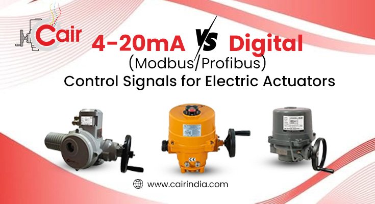
Every electric actuator spec sheet eventually comes down to one question that trips up even experienced instrumentation engineers: how exactly is this thing going to talk to your control system? Get the signal type wrong at the design stage, and you end up with a perfectly good actuator that either can’t be commanded properly or loses accuracy the moment you run cable across a large plant.
This is a genuinely technical decision, not a preference call, so let’s go through what 4-20mA and digital bus communication actually do differently, where each one holds up, and how this maps onto the control options available on our own actuator range.
The 4-20mA Standard: Why “Live Zero” Matters
The 4-20mA current loop has been the default analog standard in process industries for decades, and it’s still the backbone of modulating actuator control today. The key design detail is the “live zero” – the signal range starts at 4mA rather than 0mA. With analog control on modulating valves, 4mA represents the fully closed position and 20mA represents fully open; a 0-20mA range is deliberately avoided in practice because a reading of exactly 0mA could just as easily mean a lost or broken signal wire rather than a genuine “closed” command.
That distinction is exactly why 4-20mA remains attractive for safety-relevant applications: a genuine wire break or power loss reads as 0mA, which is instantly distinguishable from a valid “closed” command at 4mA. The control system can tell the difference between “the valve is closed” and “something’s wrong with the wiring” without any extra diagnostics layered on top.
For linear positioning, the mapping is straightforward: a 4mA input drives the valve to the fully closed 0% position, roughly 12mA commands the midpoint (around 50% open), and 20mA drives the valve to fully open. This linear relationship is what makes 4-20mA so well suited to throttling duty, where a valve needs to sit at a precise intermediate position rather than simply being fully open or fully closed.
Our own multi-turn electric actuators are built around exactly this standard, offering modulating control with a 4-20mA / 2-10V DC signal input and 4-20mA potentiometer feedback as standard, alongside auxiliary potential-free limit switches for position confirmation. If your process needs proportional flow control rather than simple on/off switching, this is the baseline configuration to start from.
Why Current Beats Voltage Over Long Cable Runs
A related but distinct question is why current (4-20mA) is generally preferred over a voltage signal like 0-10V for actuator control in industrial settings. In heavy industrial plants with long cable runs, voltage signals are prone to voltage drop caused by wire resistance over distance, which leads to inaccurate valve positioning at the far end of a long run. Current, by contrast, stays constant throughout a series circuit regardless of cable length, and current loops also offer strong immunity to electrical noise – a real consideration in plants with large motors, VFDs, and switchgear generating electromagnetic interference near instrumentation cabling.
This is why, even where our actuators support 2-10V DC as an alternative modulating input, 4-20mA remains the more common choice for installations with longer cable runs between the control room and the field-mounted actuator.
Digital Bus Communication: Modbus, Profibus, and the Rest
Digital communication takes a fundamentally different approach. Instead of a single analog value representing one variable, a digital bus – often called a fieldbus or two-wire control network – connects a group of actuators to a single digital bus controller over shared wiring. Rather than one signal per actuator, dozens of actuators can share a single communication cable, each addressed individually.
Modbus in particular has become the most widely deployed protocol in this space because of its simplicity and flexibility. It’s a relatively simple but highly functional protocol capable of exchanging binary information, analog values, device parameters, and diagnostic data, typically over a robust RS-485 physical layer using Modbus RTU or ASCII framing, with a Modbus TCP/IP variant available for integrating directly into higher-level plant automation systems.
Profibus and other fieldbus protocols work on similar principles – multiple devices sharing a communication line, each exchanging structured data with a central controller – but with different framing, addressing, and physical layer specifications depending on the standard in use.
The practical advantage over 4-20mA is the sheer amount of information available per device. A single Modbus connection can report not just position, but torque, motor temperature, running hours, fault codes, and diagnostic history – all data a single 4-20mA loop simply has no bandwidth to carry, since it’s inherently limited to one variable per pair of wires.
We’ve built this kind of connectivity into our smart valve offerings – Cair Euromatic’s motorized valves include Wi-Fi, Bluetooth, GSM, and Modbus connectivity options for customers who need to integrate actuators into a broader SCADA or IIoT monitoring layer rather than relying on point-to-point analog wiring alone. This dovetails with what we’ve covered in our piece on how smart valves are transforming water supply systems, where remote monitoring and diagnostics depend heavily on this kind of digital connectivity.
Making the Choice: A Practical Comparison
| Factor | 4-20mA Analog | Modbus/Profibus Digital |
| Wiring per actuator | Dedicated pair per device | Shared bus across many devices |
| Data carried | One variable (position or feedback) | Position, torque, diagnostics, faults, all on one connection |
| Noise immunity | High (current loop) | High, but depends on cable shielding and bus termination |
| Fault detection | Live zero distinguishes loss of signal from a valid “closed” command | Communication timeout/watchdog detects bus faults |
| Installation cost for many actuators | Higher – more cable runs | Lower – single bus serves multiple devices |
| Diagnostic depth | Minimal | Extensive |
| Legacy system compatibility | Universal, works with essentially any PLC/DCS | Requires bus-compatible controller or gateway |
Choose 4-20mA when: you’re retrofitting into an existing analog control system, you have a small number of actuators, simplicity and universal compatibility matter more than diagnostic depth, or the application is safety-critical and you want the live-zero fault detection built directly into the signal itself.
Choose Modbus/Profibus when: you’re commissioning a new facility or a large multi-valve installation where cable cost and diagnostic visibility matter, you want centralized monitoring of torque trends and fault history across many actuators, or you’re building toward a broader Industry 4.0 / IIoT monitoring strategy.
Many real installations end up using both – 4-20mA for the core position control loop on critical valves, with a Modbus overlay providing diagnostics and remote monitoring on top. Our explosion-proof electric actuators and multi-turn actuator range are both built to support this kind of layered control approach depending on your project’s specification.
Final Thoughts
Neither signal type is universally “better” – they solve different problems. 4-20mA remains the dependable, noise-resistant standard for straightforward position control, particularly where safety-relevant live-zero fault detection matters. Digital bus communication earns its place when you’re managing many actuators and need the diagnostic depth that a single analog loop simply can’t carry.
If you’re specifying actuators for a new project and aren’t sure which control architecture fits your plant, check our complete electric actuator range or our FAQ page for guidance on matching signal type to your control system.